

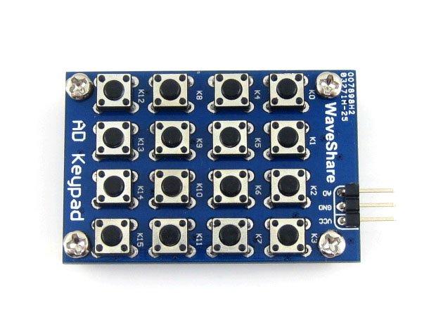
I purchased this module as part of a microcontroller kit, its an interesting little module as it has 16 buttons but with only 1 I/O line is required, an analog input. You connect this to your Wemos and read in the value.
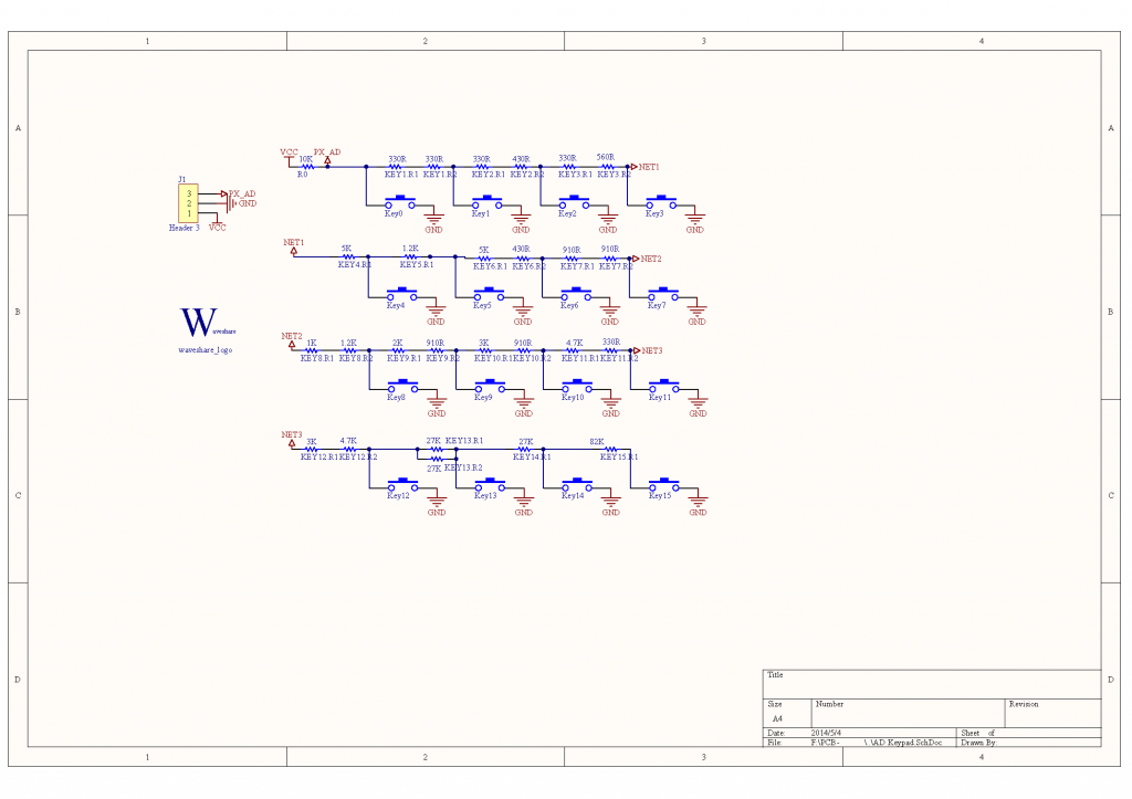
The concept is straightforward you use a resistor network as voltage dividers, and then let each button feed a different voltage to the analog pin. So by detecting the voltage you can tell which button has been pressed. You can only detect one button at a time
Here is the schematic of the module, hopefully you can see what I described earlier
Code
I put in a slight delay to try and compensate for bounce on the key press which would result in multiple values returned
[codesyntax lang=”cpp”]
#define KEYPAD_PIN A3

// milliseconds to wait, to make sure key is pressed
#define TIME_TO_WAIT 200

void setup()
{
    Serial.begin(9600);
}

void loop() {
  // put your main code here, to run repeatedly:
    int reading1 = analogRead(KEYPAD_PIN);
    // waiting
    delay(TIME_TO_WAIT);
    // reading 2nd time - to make sure key is pressed
    int reading2 = analogRead(KEYPAD_PIN);
    if(reading2 <= 1000)
    {
      Serial.println(reading2);
    }
}
[/codesyntax]
Output
Pressing the keys from K0 to K16 outputted the following in the serial monitor
1
65
129
195
258
320
383
448
510
573
636
694
755
818
881
942
So using a switch case you can use this module in your own examples, best practice would be to have a high and low value and check between the range
Links
AD Keypad 16 4×4 Accessory board matrix buttons controlled ADC AD port keyboard