

In this article we look at a digital geomagnetic sensor – this time its the BMM150. We will connect this to a micro:bit and use the Arduino IDE for development
BMM150 is a low power and low noise 3-axis digital geomagnetic sensor to be used in compass applications. The 12-pin wafer level chip scale package (WLCSP) with a footprint of 1.56 x 1.56 mm² and 0.60 mm height provides highest design flexibility to the developer of mobile devices. Applications like virtual reality or gaming on mobile devices such as mobile phones, tablet PCs or portable media players require 9-axis inertial sensing including magnetic heading information. Due to the stable performance over a large temperature range, the BMM150 is also especially suited for supporting drones in accurate heading.
BMM150 can be used with an inertial measurement unit (IMU) consisting of a 3-axis accelerometer and a 3-axis gyroscope like Bosch Sensortec’s BMI055.
Features
| Parameter | Technical data |
|---|---|
| Package | CSWLP- (12 pin) 1.56×1.56×0.6 mm³ 0.4 mm diagonal ball pitch |
| Temperature range | -40°C … +85°C |
| Digital interfaces | I²C and SPI (2 interrupt pins) |
| Resolution | 0.3μT |
| Supply voltage | VDD: 1.62V to 3.6V VDDIO: 1.2V to 3.6V |
| Zero-B offset | ±50μT |
| Non-linearity | <1% FS |
| Magnetic range typ. | ±1300μT (x,y-axis) ±2500μT (z-axis) |
| Average current consumption | 170 μA (low power preset) 500 μA (normal mode) |
| Interrupts | New data, magnetic threshold high / low |
Parts Required
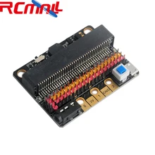
I use an expansion board which slots into the micro:bit, I find this easier to connect wires to a sensor. Here is a picture of an expansion board.
| Name | Link |
| Microbit | Micro Bit Development Board, Microbit, NRF51822 Master Card, Phython Graphic Programming |
| BMM150 | BMM150 Geomagnetic Sensor Breakout Board |
| Connecting wire | Free shipping Dupont line 120pcs 20cm male to male + male to female and female to female jumper wire |
| GPIO Expansion Board | GPIO Expansion Board For micro:bit |
Schematic/Connection
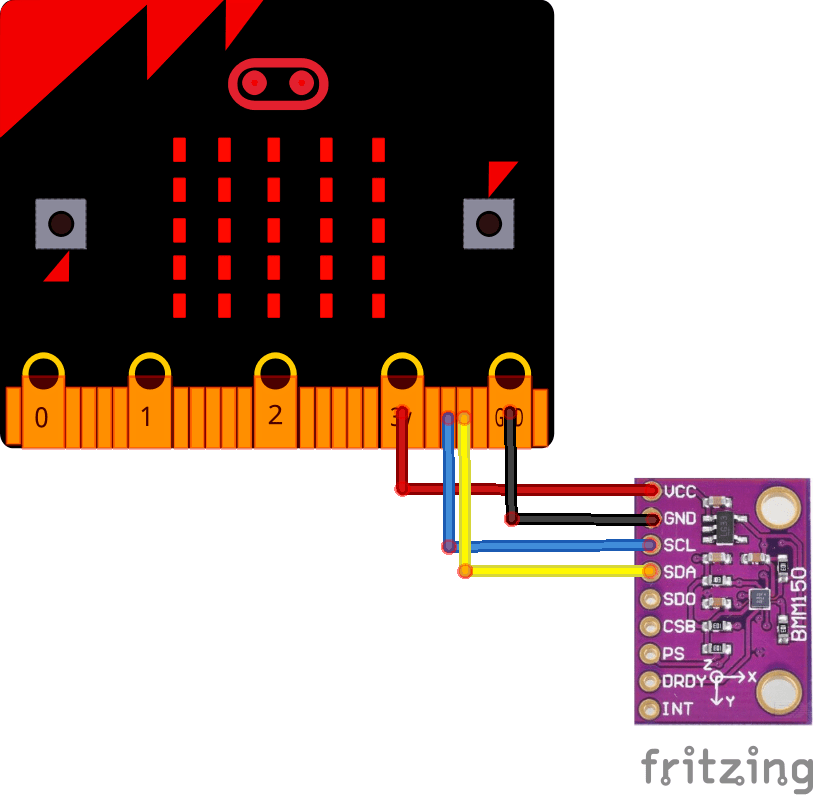
microbit and bmm150 bb
Code Example
This uses the library from https://github.com/Seeed-Studio/Grove_3_Axis_Compass_V2.0_BMM150
[codesyntax lang=”cpp”]
#include <Arduino.h>
#include <Wire.h>
// libraries
#include “bmm150.h”
#include “bmm150_defs.h”
BMM150 bmm = BMM150();
void setup()
{
Serial.begin(9600);
if(bmm.initialize() == BMM150_E_ID_NOT_CONFORM) {
Serial.println(“Chip ID can not read!”);
while(1);
} else {
Serial.println(“Initialize done!”);
}
}
void loop()
{
bmm150_mag_data value;
bmm.read_mag_data();
value.x = bmm.raw_mag_data.raw_datax;
value.y = bmm.raw_mag_data.raw_datay;
value.z = bmm.raw_mag_data.raw_dataz;
float xyHeading = atan2(value.x, value.y);
float zxHeading = atan2(value.z, value.x);
float heading = xyHeading;
if(heading < 0)
heading += 2*PI;
if(heading > 2*PI)
heading -= 2*PI;
float headingDegrees = heading * 180/M_PI;
float xyHeadingDegrees = xyHeading * 180 / M_PI;
float zxHeadingDegrees = zxHeading * 180 / M_PI;
Serial.print(“Heading: “);
Serial.println(headingDegrees);
delay(100);
}
[/codesyntax]
Output
Open the serial monitor and you should see something like this
Heading: 3.60
Heading: 11.57
Heading: 22.33
Heading: 30.79
Heading: 45.00
Heading: 68.20
Heading: 152.02
Heading: 183.25
Heading: 192.01
Heading: 192.46
Heading: 202.32
Links
https://ae-bst.resource.bosch.com/media/_tech/media/datasheets/BST-BMM150-DS001.pdf
https://github.com/BoschSensortec/BMM150-Sensor-API